Choose one of the five exercises below. Your solution should contain two part, a main part containing modeling and analyses of the particular system you have chosen using UPPAAL (3.4 or 3.5) or UPPAAL Cora. Also the solution should idal contain a shorter secondary part providing an evaluation of the tool used. You may hand in solutions in groups with at most 3 persons. The solution should be some 5-10 typeset pages. The complete report should be delivered on April 3 (Monday) at noon.
Model and analyze a control system of an elevator-system of your own design serving a number of floors (say 4 or 5) and with a number of lifts (say 2 or 3) and with a number of users being on individual floors and with individual wishes for getting to different floors. The system may:
In modelling the elevator system itself assumption of the time to get from one floor to another. Also model timing assumptions as to the arrivial of users of the elevator system. Try to validate various safety and progress properties that you may want the system to satisfy.
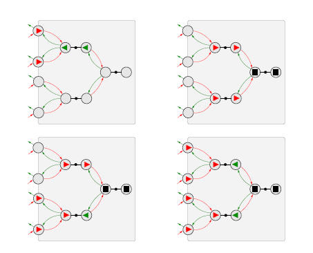
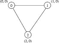
In this exercise you will consider a simple leader election protocol. The setting is the following: There are a number of interconnected network nodes. Each node has an address. The goal of the protocol is to identify the node with the lowest address is the network and elect that node to be the leader. In order to be correct, all connected nodes should have elected the same leader.
As part of the protocol, each node maintains information about which node it thinks is the leader and the number of hops (network links) to the leader. Let's say that the information at node i is stored as a pair ni=(l, h). It is perfectly valid for a node to believe that itself is the leader and in this case the number of hops to the leader is 0, e.g. n1=(1,0).
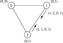
The protocol transmits messages on the form m=(source, destination, leader, hops) between the nodes. Here source is the address of the node sending the message, destination is the address of the node receiving the message, leader is information about which node source thinks is the leader and hops is the number of hops (network links) between the source and the leader.
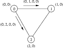
Whenever a node i receives a message m, it compares the m.leader and m.hops fields in the message with the local information ni it already has. If the leader address in the message is bigger than the address of the previous leader known to the node, i.e. m.leader > ni.leader, then the message is discarded. If the leader is the same, but the number of hops is bigger than the previous number of hops known, i.e. m.leader = ni.leader and m.hops > ni.hops, then the message is discarded. Otherwise the internal information stored at the node, i.e. ni is set to (m.leader, m.hops).
Whenever ni is updated, node i sends a message m=(i, d, ni.leader, ni.hops) to each of its neighbours d, with the exception that it does not send a message back to the source of message which triggered the update in the first place. There is an upper time bound on the arrival of the message called MSG_DELAY. Notice that there is no lower bound on the delivery and that messages might be reordered.
The final ingredient of the protocol is a timeout mechanism. If a node has not receive any messages, except those which are discarded, for more than a certain timeout period, then a timeout will happen within TIMEOUT_DELAY time units (i.e. there is a reaction delay) -- this means that there is actually a range of ]timeout; timeout+TIMEOUT_DELAY] after the last receiption of a "good" message in which a timeout will happen. Initially, the timeout is a constant INITIAL_TIMEOUT. When receiving good messages (messages which do not contain worse information than what we already got), then the timeout is set to INITIAL_TIMEOUT + TIMEOUT_DELAY + ni.hops * MESSAGE_DELAY. When a node times out, it will elect itself as the new leader and send an update message to all its neighbors.
Your task is to:
| Constant | Value |
| INITIAL_TIMEOUT | 10 |
| TIMEOUT_DELAY | 5 |
| MESSAGE_DELAY | 3 |
Notice that you should not model topology changes (network links appearing or disappearing).
A few tips for your modeling work:
In this exercise you are asked to model a solitair game and solve use UPPAAL to solve the puzzle. The game is simple. You have a 6x6 board like shown on the picture below. On the board you find a number of cars of different size (personal vehicles and trucks). The goal of the game is to move the cars by driving forward and backwards in such a way that the red car can leave the board at the exit on the right side of the board. The cars cannot turn!
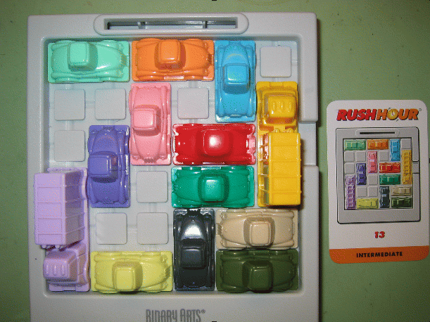
Task 1: Make a model of the game in UPPAAL.
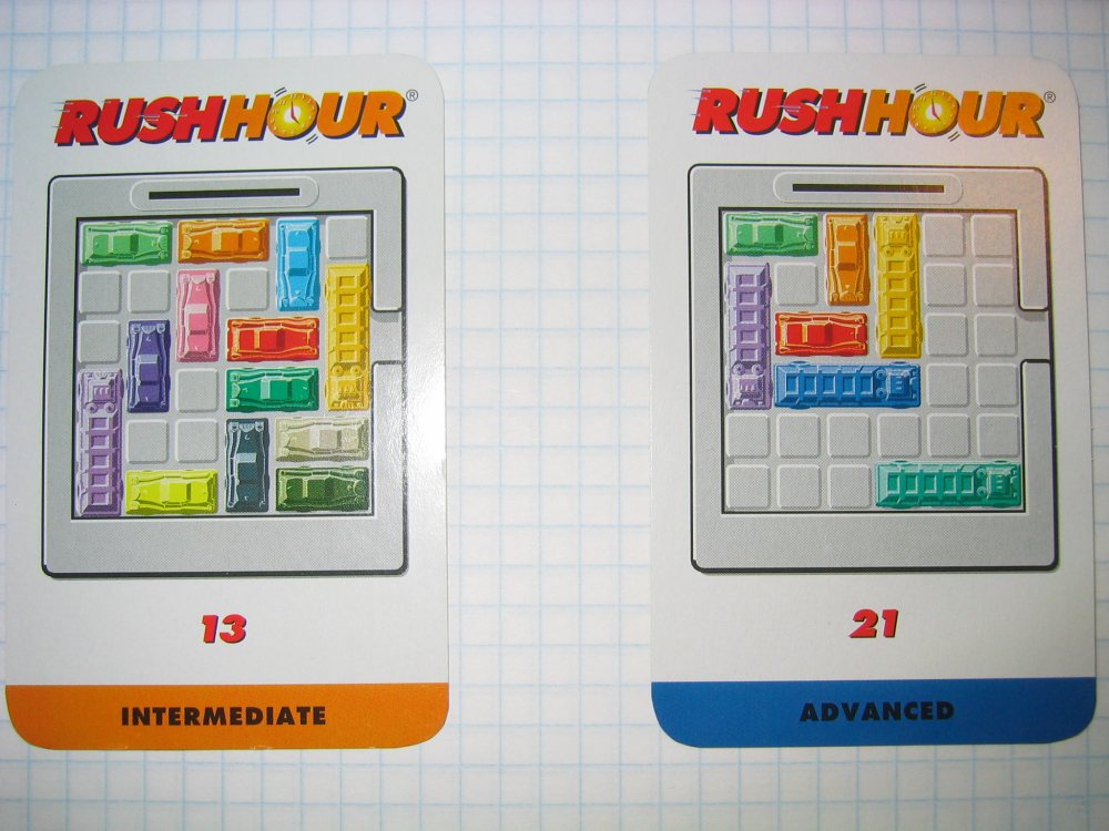
Task 2: Use your model to solve the two puzzles shown in he second picture. What is the shortest number of steps/moves needed to solve the puzzle?
Task 3: Extend your model with timing constraint. Assume that it takes a different amount of time to move the cars, e.g. 2 time units for the small ones and 3 for the trucks (you can also choose to give each car its own time). Try to experiment with different assumptions as to the number of hands/drivers, i.e. how many cars can move at the same time.
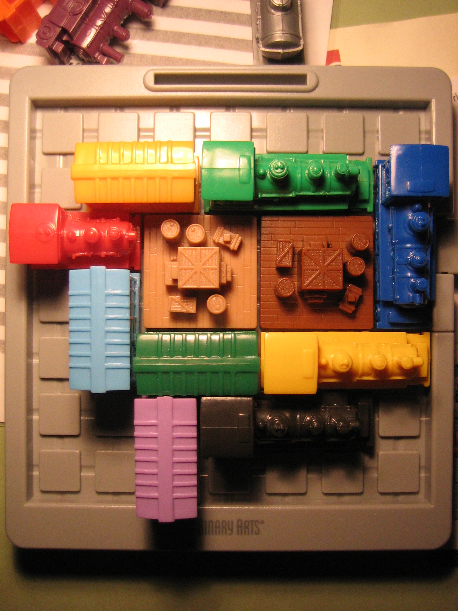
Task 4: Use Uppaal to find the fastest way of solving the puzzle (not measured in computation time, but in time it take to move all the cars). Tip: Use Uppaals diagnostic trace feature and ask for the fastest trace.NEW: you may want to deal with the more challenging RAILROAD Rush Hour, which is on a 7x7 boards and with 2x2 blockers that can move bort horizontal and vertical (see figure below):
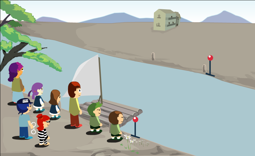
Task 1: Make an Uppaal model of it and generate a feasible schedule.
Task 2: Add temporal constraints (e.g. each adult take a certain time to cross the river with the boat) and try to find the quickest possible schedule.
Task 3: Try other parameters and constraints for this game. Determine what is the feasibility limit depending on the number of boys, girls, prisonners.
Lithographic machines, called wafer scanners, are used within the semiconductor
industry to project chip designs on slices of silicon which are called wafers. A
key
performance characteristic of wafer scanners is throughput. In order to maximize
throughput, a controller must have a strategy that optimizes throughput in the
absence of errors. Moreover, no deadlock may ever arise since resolution of the
deadlock means that the machine is off-line for a relatively long period (or at
least
has a suboptimal throughput).
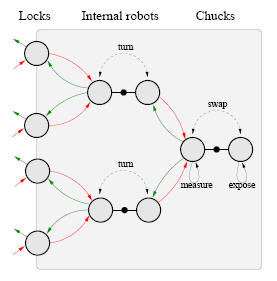
The above figure schematically depicts a possible design of the wafer flow
within an
Extreme Ultra Violet machine (EUV machine), which is a particular type of wafer
scanner that is currently being developed by ASML (EUV refers to the kind of
radiation that is used to expose the wafers). The inside of an EUV machine is
kept vacuum as EUV light is absorbed by air. The wafer flow is as follows. First,
the
track robot (which is not shown) puts a wafer in one of the four locks. This
lock is depressurized, and then the wafer is picked
up by one of the two internal robots. Each internal robot has two arms that can
each
hold a wafer and that are opposite to each other. The internal robot turns and
puts the wafer on the closest chuck, which is in
the so-called measure position. The wafer is measured and a chuck swap is
performed.
The chuck with the measured wafer now is in the expose position and the wafer
is
exposed. After another chuck swap, the exposed wafer is picked up by one of the
internal
robots which turns and puts it in adepressurized lock. After the lock has been
pressurized, the track robot removes
the exposed wafer from the machine. Each wafer thus has a fixed recipe for its
route: lock - internal robot - chuck - internal robot - lock. There is a choice
which
locks, internal robots and chucks are used by a wafer. An obvious question that
arises is why we not let the unexposed wafers flow through the upper two locks
and let the exposed wafers exit through the lower two locks. In that case there
are no crossing material paths which means that there is no deadlock possible.
The answer is twofold. First, if locks are unidirectional then filling the
machine
from the initial, empty, state takes unnecessarily long. Second, if locks are
unidirectional
then the depressurization operation might become critical instead of the
exposure, since depressurization takes more than twice as long as exposure. This
is bad, since the lens which is used during the exposure is the most expensive
part
of the wafer scanner and must therefore have a maximal utilization.